Separation
Gold Extraction Equipment
Gold extraction equipment performs the leaching, adsorption, desorption and recovery stages that follow grinding. The circuit you build depends on your choice of CIP, CIL or zinc precipitation. These machines provide the core processing steps for a gold recovery plant.
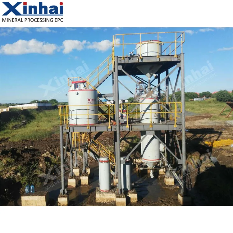
Equipment in this category
Decisions on tank sizing, carbon handling and elution batch capacity shape capital and operating cost. Cyanide management and ore testwork are critical inputs for each choice.
The machines cover the full extraction sequence. The leaching agitation tank dissolves gold into solution. Carbon screens and adsorption columns capture gold-loaded carbon. The desorption electrolysis system recovers gold from carbon. For zinc precipitation circuits, the zinc powder feeding and mixing unit is added. Support equipment includes the air lifter, deoxygenation tower and multi-layer washing thickener.
- Leaching Agitation Tank
- Air Lifter
- Carbon Screen
- Desorption Electrolysis System
- Double-Impeller Leaching Tankcat.
- Carbon Regeneration Kilncat.
- Multi-Layer Washing Thickenercat.
- Deoxygenation Towercat.
- Carbon Adsorption Columncat.
- Zinc Powder Feeding and Mixing Unitcat.
Names marked cat. follow the equipment handbook rather than the product catalogue naming.
What decides the selection
Start with circuit type: CIP, CIL or zinc precipitation. Slurry throughput and gold grade define tank volumes and carbon concentration targets. Leaching residence time and elution batch size follow from metallurgical testwork. Cyanide management and site safety requirements influence equipment layout and materials selection. Each variable is interdependent; testwork on your specific orebody reduces risk.
- Circuit type (CIP, CIL or zinc precipitation)
- Slurry throughput
- Gold grade
- Leaching residence time
- Carbon concentration
- Elution batch size
- Safety and environmental requirements
- Cyanide management
Gold cyanidation involves toxic chemicals and occupational health risk. This page sets out equipment and circuit relationships only. It does not substitute for compliant design or site safety procedures.
Technical parameters
85 models across 6 machine types, as published in the Xinhai equipment application manual.
These are standard-model catalogue figures. Actual capacity, power draw and wear life shift with ore properties, feed gradation and circuit conditions. Treat them as a shortlisting aid, not as a performance guarantee for your duty. Final selection rests on testwork, flowsheet calculation and a written confirmation from the manufacturer.
Dual-Impeller Leaching Agitation Tank
| Model | Tank Diameter (mm) | Tank Height (mm) | Effective Volume( m3 ) | Motor Power (kW) | Equipment Weight (kg) |
|---|---|---|---|---|---|
| SJ2.0×2.5 | 2000 | 2500 | 6 | 4 | 2144 |
| SJ2.5×2.5 | 2500 | 2500 | 6 | 4 | 2729 |
| SJ2.5×3.15 | 2500 | 3150 | 13 | 4 | 3095 |
| SJ3.15×3.55 | 3150 | 3550 | 24 | 5.5 | 4320 |
| SJ3.5×4.0 | 3500 | 4000 | 30 | 5.5 | 5429 |
| SJ4.0×4.5 | 4000 | 4500 | 48 | 7.5 | 7830 |
| SJ4.5×5.0 | 4500 | 5000 | 71.57 | 7.5 | 10865 |
| SJ5.0×5.6 | 5000 | 5600 | 98 | 11 | 15365 |
| SJ5.5×6.0 | 5500 | 6000 | 112 | 15 | 18800 |
| SJ6.0×6.5 | 6000 | 6500 | 166.7 | 18.5 | 20545 |
| SJ6.5×7.0 | 6500 | 7000 | 195 | 22 | 25731 |
| SJ7.0×7.5 | 7000 | 7500 | 245.4 | 22 | 29000 |
| SJ7.5×8.0 | 7500 | 8000 | 268.6 | 22 | 32220 |
| SJ8.0×8.5 | 8000 | 8500 | 319 | 30 | 42470 |
| SJ8.5×9.0 | 8500 | 9000 | 395 | 30 | 45900 |
| SJ9.0×9.5 | 9000 | 9500 | 540 | Customized based on client's needs | |
| SJ9.5×10.0 | 9500 | 10000 | 640 | ||
| SJ10.0×10.5 | 10000 | 10500 | 762 | ||
| SJ11.0×11.5 | 11000 | 11500 | 998 | ||
| SJ12.0×12.5 | 12000 | 12500 | 1345 | ||
| SJ13.0×14.0 | 13000 | 14000 | 1700 | ||
| SJ14.0×15.0 | 14000 | 15000 | 2100 | ||
| SJ15.0×16.0 | 15000 | 16000 | 2600 |
Carbon Screen
| Model | Dimensions (mm) | Screen Inner Diameter (mm) | Screen Length (mm) | Weight (kg) |
|---|---|---|---|---|
| SY-100 | \phi 100 \times 470 | 100 | 370 | 2.87 |
| SY-150 | \phi 150 \times 800 | 150 | 600 | 8.92 |
| SY-200 | \phi 200 \times 900 | 200 | 700 | 10.97 |
| SY-250 | \phi 250 \times 1000 | 250 | 800 | 14.52 |
| SY-300 | \phi 300 \times 1300 | 300 | 1000 | 17.16 |
| SY-500 | \phi 500 \times 1300 | 500 | 1000 | 35.72 |
| SY-600 | \phi 600 \times 1300 | 600 | 1000 | 39.08 |
| SY-800 | \phi 800 \times 1800 | 800 | 1500 | 112.18 |
| SY-1000 | \phi 1000 \times 2500 | 1000 | 2000 | 147.91 |
Air Lifter
| Model | Carbon Transfer Box Dimensions (mm) | Suction Box (mm) | Carbon Lifting Pipe Diameter (mm) | Carbon Lifting Pipe Length (mm) |
|---|---|---|---|---|
| KT-60 | 400×400×450 | Φ300×200 | Φ60 | 2250-4690 |
| KT-80 | 350×350×350 | Φ350×250 | Φ89 | 4760-5760 |
| KT-100 | 350×350×350 | Φ400×250 | Φ108 | 2190-7190 |
| KT-125 | 420×370×545 | Φ520×250 | Φ133 | 3850-5350 |
| KT-150 | 450×400×550 | Φ550×250 | Φ159 | 3600-6000 |
| KT-200 | 710×708×700 | Φ540×648 | Φ219 | 5500-9000 |
| KT-300 | Φ854×1450 | Φ700×792 | Φ325 | 9800-10800 |
| Model | Applicable Scale | Basic System Equipment Details | System Instrument Details | Operating Parameters | |
|---|---|---|---|---|---|
| Mine Scale (t/d) | Ore Grade (g/t) | ||||
| GJD-200 | <150 | 2-8 | Desorption Column Filter Electrolytic Cell Circulation Pump Electric Heater Carbon Injector Air Compressor Desorption Solution Tank Clean Water Pump Magnetic Pump Carbon Storage Tank Control Cabinet Silicon Rectifier Cabinet | Resistant Remote Diaphragm Pressure Gauge Pressure Indication Regulator Diaphragm Pressure Gauge Vortex Flowmeter Flow Totalizer Thermal Temperature Gauge Temperature Sensor Instrument Diaphragm Pressure Gauge Level Gauge Temperature Sensor Instrument Temperature Indication Regulator | Desorption Solution: pH: ≥ 13.5 Number of Uses: Unlimited Electrolysis Start Temperature: 100-110°C Electrolysis End Temperature: 150°C Pressure at 150°C: Top of Desorption Column: 0.5-0.57 MPa Electrolytic Cell: 0.45-0.52 MPa |
| GJD-300 | 150-300 | ||||
| GJD-500 | 300-500 | ||||
| GJD-1000 | 600-1000 | ||||
| GJD-1500 | |||||
| GJD-2000 | 1300-2000 | 2-20 | |||
| GJD-3000 | |||||
| GJD-5000 | 3000-4000 | ||||
| GJD-6000 | |||||
| GJD-8000 | 5000-7000 | ||||
| GJD-10000 |
Carbon Regeneration Furnace
| Model | Maximum Processing Capacity (kg/d) | Heating Power (kW) | Insulation Power (kW) | Drum Rotation Speed (r/min) | Drum Rotation Speed (mm) | Power (kW) |
|---|---|---|---|---|---|---|
| ZSL-1000 | 1000 | 110 | 65 | 0.5-3 | 7792×1795×1700 | 1.5+0.75 |
| ZSL-2000 | 2000 | 180 | 100 | 0.5-3 | 8785×1900×1995 | 2.2+1.1 |
| ZSL-3000 | 3000 | 240 | 200 | 0.5-3 | 10200×1900×1995 | 2.2+1.1 |
| ZSL-4000 | 4000 | 240 | 200 | 0.5-3 | 10200×1900×1995 | 2.2+1.1 |
| ZSL-5000 | 5000 | 280 | 200 | 0.5-3 | 11411×1900×2022 | 3+1.1 |
Multi-Deck Scrubbing Thickener
| Model | Thickening Tank Diameter (m) | Number of Layers | Settling Area ( m2 ) | Rake Arm Rotation Speed (r/min) | Maximum Processing Capacity (t/d) | Motor Power (kW) | Weight (kg) |
|---|---|---|---|---|---|---|---|
| 2NZSG-6 | 6 | 2 | 28.3 | 0.2481 | 15-50 | 2.2 | 19639 |
| 2NZSG-9 | 9 | 2 | 63 | 0.28 | 88 | 4 | 41694 |
| 2NZSG-12 | 12 | 2 | 113 | 0.2 | 50-250 | 5.5 | 86713 |
| 2NZSG-15 | 15 | 2 | 177 | 0.1 | 70-350 | 5.5 | 10750 |
| 3NZSG-6 | 6 | 3 | 28.3 | 0.2481 | 15-50 | 2.2 | 32163 |
| 3NZSG-9 | 9 | 3 | 63 | 0.28 | 88 | 4 | 54628 |
| 3NZSG-12 | 12 | 3 | 113 | 0.2 | 50-250 | 5.5 | 119650 |
| 3NZSG-15 | 15 | 3 | 177 | 0.1 | 70-350 | 5.5 | 150000 |
| Model | Tower Dimensions (mm) | Working Pressure Vacuum Degree (MPa) | Working Temperature | Spraying Volume ( m^3/m^2 \cdot h ) | Weight (kg) |
|---|---|---|---|---|---|
| TY-830 | \phi 800×3000 | 0.09~0.096 | Normal Temperature | 1.56 | 747 |
| TY-1030 | \phi 1000×3000 | 956 | |||
| TY-1236 | \phi 1200×3600 | 1232 | |||
| TY-1536 | \phi 1500×3600 | 1632 | |||
| TY-1840 | \phi 1800×4000 | 2 | 2042 | ||
| TY-2040 | \phi 2000×4000 | 0.2 | 3900 | ||
| TY-2440 | \phi 2400×4000 | 4524 |
Carbon Adsorption Column
| Type | Model | Tower Dimensions (mm) | Liquid Supply Pressure (MPa) | Carbon Load (kg) | Adsorption Liquid Volume ( m^3/h ) | Weight (kg) |
|---|---|---|---|---|---|---|
| Open Type | XFZK0340 | φ300×4000 | ≤0.2 | 300 | 8 | 385 |
| XFZK0528 | φ500×2800 | 300 | 8 | 670 | ||
| XFZK1524 | φ1500×2400 | 1000 | 50 | 1680 | ||
| XFZK2046 | φ2000×4600 | ≤0.4 | 5000 | 300 | 3220 | |
| XFZK3060 | φ3000×6000 | 6000 | 600 | 8121 | ||
| Closed Type | XFZB1025 | φ1000×2500 | ≤0.2 | 500 | 40 | 1100 |
| XFZB1030 | φ1000×3000 | 500 | 40 | 1173 | ||
| XFZB1230 | φ1200×3000 | 600 | 40 | 1509 | ||
| XFZB1236 | φ1200×3600 | 1000 | 50 | 1617 | ||
| XFZB1530 | φ1500×3000 | 1000 | 50 | 3400 | ||
| XFZB2045 | φ2000×4500 | ≤0.4 | 5000 | 300 | 4190 | |
| XFZB2250 | φ2200×5000 | 5000 | 300 | 3714 | ||
| XFZB2256 | φ2200×5600 | 5000 | 300 | 6224 | ||
| XFZB2460 | φ2400×6000 | 10000 | 600 | 6140 |
ISO 9001 / ISO 14001 / ISO 45001 / ISO 9712 / CE / CSA W47.1 / CNAS accredited laboratory
Send the duty, get a sized proposal
Tell us the ore, the throughput and the target product. Our process engineers come back with a flowsheet position, a model shortlist and the testwork we would need to confirm it.