Separation
Flotation Equipment
Flotation cells use aeration, agitation and froth to separate valuable minerals from gangue. They are the primary separation stage in sulphide, oxide and industrial mineral circuits.
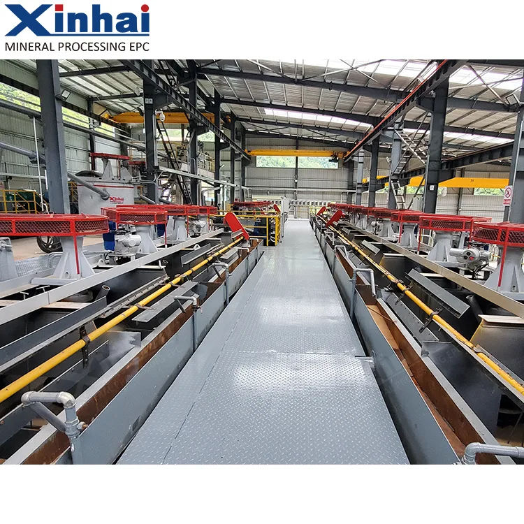
Equipment in this category
Mine owners and project managers must choose between mechanical, air-inflation and column designs, each suited to different particle sizes, throughputs and circuit layouts. Testwork on ore floatability, particle size and pulp density determines cell volume and circuit configuration.
Mechanical cells like SF and BF are self-aspirating and often used in rougher and scavenger stages. Forced-air designs such as KYF and XCF suit higher-capacity duties. The Flotation Column provides fine cleaning, and the Coarse Particle Cell handles coarse feeds.
- SF Flotation Cell
- BF Flotation Cell
- KYF Air Inflation Flotation Cell
- JJF Flotation
- Wemco Flotation
- XCF Flotation Cellcat.
- Coarse Particle Flotation Cellcat.
- Flotation Columncat.
Names marked cat. follow the equipment handbook rather than the product catalogue naming.
What decides the selection
Start with ore floatability testwork to select the flotation regime. Particle size distribution and pulp density define cell volume, aeration rate and agitation intensity. Circuit stage configuration and froth control targets follow from kinetic data. Specific energy and wear part life inform total cost of ownership. Recoveries from lab or pilot tests apply only to the tested sample and conditions, not as general equipment guarantees.
- Ore floatability
- Particle size
- Pulp density
- Cell volume
- Aeration rate and agitation intensity
- Number of circuit stages
- Froth depth control
- Specific energy consumption and wear parts
Recoveries quoted in the catalogue apply only to the corresponding ore sample, reagent regime and circuit conditions. They are not a general guaranteed value for the equipment.
Technical parameters
78 models across 4 machine types, as published in the Xinhai equipment application manual.
These are standard-model catalogue figures. Actual capacity, power draw and wear life shift with ore properties, feed gradation and circuit conditions. Treat them as a shortlisting aid, not as a performance guarantee for your duty. Final selection rests on testwork, flowsheet calculation and a written confirmation from the manufacturer.
Technical parameters
| Type | Features | Models | Advantages | Disadvantages |
|---|---|---|---|---|
| Mechanical Agitation Flotation Machine | The aeration and agitation of the pulp are completed by the mechanical agitation device composed of an impeller and a stator. It belongs to the external air self-suction flotation machine, usually with top air suction, i.e., air is drawn near the mechanical agitation device at the bottom of the flotation cell. | BF Type SF Type | Self-suck air and pulp; easy to achieve self-flow for returning middling; few auxiliary devices; neat equipment configuration; easy operation and maintenance. | Low aeration volume, high power consumption, heavy wear. |
| Air-Inflation Agitation Flotation Machine | Equipped with a mechanical agitation device and a specially designed external blower to force air in. The mechanical agitator only serves to agitate the pulp and distribute the airflow, while the air is mainly introduced by an external blower. The pulp aeration and agitation are separated. | XCF Type KYF Type CLF Type | The air volume can be adjusted as needed, maintaining constancy, which helps improve the flotation machine's processing capacity and separation indexes; the impeller doesn't have to suck air, so it runs at low speed, consumes less power, has less wear, and fragile minerals are less likely to become muddy; due to high capacity and shallow cells, the power consumption per unit is low. | Requires an additional air compression system. |
| Air-Inflation Flotation Machine | No mechanical agitator or transmission components, with a specially installed blower providing air for aeration. | Flotation Column | Simple structure, easy to manufacture. | Without an agitator, the flotation effect is somewhat compromised; aerators are prone to calcium buildup, affecting air dispersion. |
SF Type Mechanical Agitation Flotation Machine
| Model | Effective Volume (m3) | Processing Capacity (m3/min) | Max Air Intake (m3/m2.min) | Motor Power (kW) | Dimensions (mm) | Single Tank Weight (kg) | |
|---|---|---|---|---|---|---|---|
| Agitation | Scraper | ||||||
| SF-0.37 | 0.37 | 0.2-0.4 | 1 | 1.5 | 0.55 | 700×700×750 | 405 |
| SF-0.7 | 0.7 | 0.3-0.7 | 1 | 3 | 1.1 | 900×900×860 | 640 |
| SF-1.2 | 1.2 | 0.6-1.3 | 1 | 5.5 | 1.1 | 1100×1100×1100 | 1375 |
| SF-2 | 2 | 1.5-2.5 | 1 | 11 | 1.5 | 1600×1600×1150 | 2150 |
| SF-2.8 | 2.8 | 1.5-3.1 | 1 | 11 | 1.5 | 1700×1600×1150 | 2230 |
| SF-4 | 4 | 2-4 | 1 | 15 | 1.5 | 1850×2050×1200 | 2790 |
| SF-6 | 6 | 3-6 | 1 | 30 | 2.2 | 2200×2286×1263 | 3620 |
| SF-8 | 8 | 4-8 | 1 | 30 | 2.2 | 2200×2900×1400 | 4500 |
| SF-16 | 16 | 5-16 | 1 | 45 | 1.5 | 2850×3800×1700 | 6940 |
| SF-20 | 20 | 5-20 | 1 | 55 | 1.5 | 2850×3800×2000 | 9800 |
BF Mechanical Agitation Flotation Machine
| Model | Effective Volume (m3) | Processing Capacity (m3/min) | Max Air Intake (m3/m2.min) | Motor Power (kW) | Dimensions (mm) | Single Tank Weight (kg) | |
|---|---|---|---|---|---|---|---|
| Agitation | Scraper | ||||||
| BF-0.05 | 0.05 | 0.01-0.05 | 1 | 0.55 | 0.18 | 390×390×340 | 105 |
| BF-0.15 | 0.15 | 0.06-0.16 | 1 | 1.5 | 0.55 | 550×550×600 | 240 |
| BF-0.25 | 0.25 | 0.12-0.28 | 1 | 1.5 | 0.55 | 600×600×700 | 340 |
| BF-0.37 | 0.37 | 0.2-0.4 | 1 | 1.5 | 0.55 | 700×700×750 | 405 |
| BF-0.7 | 0.7 | 0.3-0.7 | 1 | 3 | 1.1 | 900×900×860 | 640 |
| BF-1.2 | 1.2 | 0.6-1.3 | 1 | 5.5 | 1.1 | 1100×1100×1100 | 1370 |
| BF-2 | 2 | 1.5-2.5 | 1 | 11 | 1.5 | 1600×1600×1150 | 2150 |
| BF-2.8 | 2.8 | 1.5-3.1 | 1 | 11 | 1.5 | 1700×1600×1150 | 2230 |
| BF-4 | 4 | 2-4 | 1 | 15 | 1.5 | 1850×2050×1200 | 2790 |
| BF-6 | 6 | 3-6 | 1 | 30 | 2.2 | 2200×2286×1263 | 3620 |
| BF-8 | 8 | 4-8 | 1 | 30 | 2.2 | 2200×2900×1400 | 4500 |
| BF-10 | 10 | 5-10 | 1 | 30 | 2.2 | 2200×2900×1700 | 4750 |
| BF-16 | 16 | 5-16 | 1 | 45 | 1.5 | 2850×3800×1700 | 6940 |
| BF-20 | 20 | 5-20 | 1 | 55 | 1.5 | 2850×3800×2000 | 9800 |
| BF-24 | 24 | 5-24 | 1 | 55 | 1.5 | 3150×4150×2000 | 10150 |
| Model | Effective Volume (m3) | Processing Capacity (m3/min) | Max Air Intake (m3/m2.min) | Blower Air Pressure (Kpa) | Motor Power (kW) | Dimensions (mm) | Single Tank Weight (kg) | |
|---|---|---|---|---|---|---|---|---|
| Agitation | Scraper | |||||||
| XCF-1 | 1 | 0.2-1 | 2 | ≥12.6 | 5.5 | 0.75 | 1000×1000×1100 | 1154 |
| KYF-1 | 4 | 903 | ||||||
| XCF-2 | 2 | 0.4-2 | 2 | ≥14.7 | 7.5 | 1.1 | 1300×1300×1230 | 1659 |
| KYF-2 | 5.5 | 1419 | ||||||
| XCF-4 | 4 | 1.2-4 | 2 | ≥19.8 | 15 | 1.5 | 1800×1800×1500 | 2170 |
| KYF-4 | 11 | 1920 | ||||||
| XCF-8 | 8 | 3-8 | 2 | ≥21.6 | 22 | 1.5 | 2200×2200×1950 | 4380 |
| KYF-8 | 15 | 3885 | ||||||
| XCF-10 | 10 | 4-10 | 2 | ≥21.6 | 30 | 1.5 | 2370×2370×2100 | 4325 |
| KYF-10 | 22 | 4010 | ||||||
| XCF-16 | 16 | 4-16 | 2 | ≥25.5 | 37 | 1.5 | 2800×2800×2400 | 6205 |
| KYF-16 | 30 | 5705 | ||||||
| XCF-20 | 20 | 4-20 | 2 | ≥27 | 45 | 1.5 | 2920×2920×2730 | 7586 |
| KYF-20 | 37 | 6667 | ||||||
| XCF-24 | 24 | 4-24 | 2 | ≥30.4 | 55 | 1.5 | 3100×3100×2900 | 9935 |
| KYF-24 | 37 | 8265 | ||||||
| XCF-30 | 30 | 7-30 | 2 | ≥31.6 | 55 | 1.5 | 3500×3500×3025 | 12005 |
| KYF-30 | 45 | 10455 | ||||||
| XCF-38 | 38 | 10-38 | 2 | ≥34.3 | 75 | 1.5 | 3600×3600×3400 | 13200 |
| KYF-38 | 55 | 11566 | ||||||
| XCF-40 | 40 | 10-40 | 2 | ≥35 | 75 | 1.5 | 3800×3800×3400 | 13750 |
| KYF-40 | 55 | 12116 | ||||||
| XCF-50 | 50 | 10-40 | 2 | ≥42 | 90 | 2.2 | 4200×4200×3600 | 14500 |
| KYF-50 | 75 | 13800 |
| Model | Tank Diameter (mm) | Tank Height (mm) | Effective Volume ( m3 ) | Processing Capacity ( m^3/min ) | Maximum Air Inflation ( m^3/m^2.min ) | Blower Air Pressure (Kpa) | Motor Power (kW) |
|---|---|---|---|---|---|---|---|
| KYF-50 | 4600 | 3500 | 50 | 5-25 | 1.5 | ≥ 42 | 75 |
| KYF-70 | 5200 | 4200 | 70 | 20-50 | 1.5 | ≥ 45 | 110 |
| KYF-100 | 5800 | 4560 | 100 | 20-60 | 1.5 | ≥ 52 | 185 |
| KYF-130 | 6200 | 4800 | 130 | 20-60 | 1.5 | ≥ 55 | 220 |
| KYF-160 | 6800 | 5500 | 160 | 20-60 | 1.5 | ≥ 60 | 250 |
| KYF-200 | 7500 | 5600 | 200 | 20-100 | 1.5 | ≥ 65 | 280 |
| Model | Effective Volume (m3) | Feed Particle Size (mm) | Processing Capacity (m3/min) | Blower Air Pressure (Kpa) | Maximum Air Inflation (m3/m2.min) | Motor Power (kW) | Dimensions (mm) | Single Tank Weight (kg) | ||
|---|---|---|---|---|---|---|---|---|---|---|
| Agitation | Scraper | |||||||||
| CLF-2 | Suction Tank | 2 | < 1 | 1-2 | ≥ 15 | 2 | 7.5 | 1.5 | 1200×1600×1250 | 1591 |
| Direct Current Tank | 5.5 | 1481 | ||||||||
| CLF-4 | Suction Tank | 4 | < 1 | 1-4 | ≥ 19.8 | 2 | 15 | 1.5 | 1600×2100×1500 | 3202 |
| Direct Current Tank | 11 | 2955 | ||||||||
| CLF-8 | Suction Tank | 8 | < 1 | 1-8 | ≥ 21.6 | 2 | 22 | 1.5 | 2500×1900×1930 | 4690 |
| Direct Current Tank | 15 | 4360 | ||||||||
| CLF-16 | Suction Tank | 16 | < 1 | 5-16 | ≥ 25 | 2 | 45 | 1.5 | 2500×3200×2400 | 6975 |
| Direct Current Tank | 37 | 6350 |
Flotation Column
| Model | Column Diameter (mm) | Column Height (mm) | Production Capacity | Circulation Pump Power (kW) | Wet Weight (t) | |
|---|---|---|---|---|---|---|
| Slurry ( m^3/h ) | Dry Ore Quantity (t/h) | |||||
| FXZ-10 | 1000 | 5000 | 30-60 | 3-5 | 15 | 5.4 |
| FXZ-15 | 1500 | 5000 | 60-80 | 5-7 | 30 | 11.8 |
| FXZ-20 | 2000 | 5500 | 80-150 | 7-10 | 45 | 20.7 |
| FXZ-30 | 3000 | 5500 | 200-300 | 15-25 | 75 | 45.3 |
| FXZ-40 | 4000 | 6200 | 300-450 | 25-35 | 110 | 77.8 |
| FXZ-50 | 5000 | 6200 | 450-600 | 35-45 | 132 | 116.2 |
| FXZ-60 | 6000 | 6200 | 600-800 | 45-55 | 200 | 143.5 |
ISO 9001 / ISO 14001 / ISO 45001 / ISO 9712 / CE / CSA W47.1 / CNAS accredited laboratory
Send the duty, get a sized proposal
Tell us the ore, the throughput and the target product. Our process engineers come back with a flowsheet position, a model shortlist and the testwork we would need to confirm it.