Separation
Gravity Separation Equipment
Gravity separation equipment recovers minerals based on density difference in a fluid medium. These units follow comminution and sizing stages in the flowsheet, and they produce a concentrate of higher-density valuable minerals while discarding lower-density gangue.
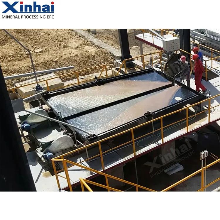
Equipment in this category
This page helps you choose among the main gravity separator types: concentrating tables, jigs, spiral chutes, and centrifugal concentrators. Your decision will depend on liberation size, feed density, throughput needs, and the recovery target for your specific orebody.
Concentrating tables handle finer feeds and produce high-grade concentrates. Jigs treat coarser particles with high unit throughput. Spiral chutes suit moderate size ranges at low cost per tonne. Centrifugal concentrators recover fine heavy minerals that would otherwise be lost. Each type has variants optimised for particular feed characteristics.
- Concentrating Table (Shaking Table)
- Jig
- Spiral Chute
- Sawtooth Wave Jigcat.
- Agitation Chutecat.
- Water-Jacket Centrifugal Concentratorcat.
- Centrifugal Concentratorcat.
- Vibrating Cone Concentratorcat.
Names marked cat. follow the equipment handbook rather than the product catalogue naming.
What decides the selection
Selecting a gravity circuit starts with laboratory testwork on your sample. Density difference and liberation size determine which gravity forces are effective. Feed density and water consumption are optimised during pilot trials. Throughput per unit area scales from batch tests, while stroke and frequency are set by the specific machine design and particle behaviour. The recovery target ties these choices to a measurable economic goal.
- Density difference between minerals
- Liberation size
- Size range treated
- Feed density
- Throughput per unit area
- Stroke and stroke frequency
- Water consumption
- Recovery target
Technical parameters
64 models across 7 machine types, as published in the Xinhai equipment application manual.
These are standard-model catalogue figures. Actual capacity, power draw and wear life shift with ore properties, feed gradation and circuit conditions. Treat them as a shortlisting aid, not as a performance guarantee for your duty. Final selection rests on testwork, flowsheet calculation and a written confirmation from the manufacturer.
Sawtooth Wave Jig
| Item Parameters Model | Jigging Chamber | Diaphragm | Feed Size (mm) | Adding Water Yield Under Screen ( m^3/t ) | Water Pressure | Handling Capacity (t/h) | Motor Power (kW) | Dimension (mm) | Weight (kg) | Remarks | ||
|---|---|---|---|---|---|---|---|---|---|---|---|---|
| Shape | Area ( m2 ) | Stroke (mm) | Jig Frequency (times/min) | |||||||||
| JT0.57-1 | Trapezoid | 0.57 | 8.5-1210-1712-21 | 80-180 | <6 | ≥0.05 | 1.5-3 | 1.5 | 1550×780×1530 | 610 | ||
| JT1-1 | Trapezoid | 1.04 | <10 | 2.5-5 | 2.2 | 2270×1110×1890 | 900 | |||||
| JT2-2 | Rectangle | 2.28 | <10 | 3 | 3225×1550×2050 | 1640 | ||||||
| JT3-1 | Trapezoid | 3 | 12-30 | 50-125 | <10 | ≥0.05 | 7.5-15 | 5.5 | 2745×2000×3030 | 3085 | ||
| JT4-2 | Rectangle | 4 | 25-57 | <25 | 7.5 | 4240×1990×2750 | 3098 | Large Particle Jig | ||||
| JT4-2A | Rectangle | 4 | 25-57 | <25 | 4x2 | 4240×1990×2750 | 3500 | Twin Drive Of Large Particle Jig | ||||
| JT5-2 | Trapezoid | 4.86 | <10 | 7.5 | 3600×2000×2600 | 4500 |
6-S Shaking Table
| Model | 6-S 7.6 | 6-S 4.08 | 6-S 1.95 | 6-S 0.5 | |||
|---|---|---|---|---|---|---|---|
| Bed Surface Type | Coarse Sand Bed Surface | Fine Sand Bed Surface | Slurry Bed Surface | 3 Kinds Of Bed Surfaces Selectable | |||
| Beneficiation Area Of Bed Surface (M2) | 7.6 | 7.6 | 7.6 | 4.08 | 1.95 | 0.5 | |
| Bed Surface Dimension | Length (mm) | 4500 | 4500 | 4500 | 3000 | 2100 | 1100 |
| Width Of Driving End (mm) | 1850 | 1850 | 1850 | 1320 | 1050 | 500 | |
| Width Of Concentration End (mm) | 1550 | 1550 | 1550 | 1100 | 850 | 430 | |
| Feed Size (mm) | 0.5-2 | 0.074-0.5 | 0-0.074 | Mineral sand: 0-2Slurry: 0-0.074 | |||
| Capacity (t/h) | 1-1.2 | 0.5-1 | 0.3-0.5 | 0.4-1.5 | 0.3-0.8 | 0.05-0.2 | |
| Feed Density (%) | 20-30 | 18-25 | 15-20 | 10-30 | |||
| Stroke (mm) | 16-22 | 11-16 | 8-16 | 6-30 | 12-28 | 9-17 | |
| Jig Frequency (r/min) | 220 | 250 | 280 | 210-320 | 250-450 | 280-460 | |
| Water Consumption (t/h) | 0.7-1 | 0.4-0.7 | 0.4-0.7 | 0.3-1.5 | 0.2-1 | 0.1-0.5 | |
| Notch Groove Section Shape | Rectangle | Sawtooth Wave | Triangle | Rectangle, Sawtooth Wave and Triangle Selectable | |||
| Motor Power (kW) | 1.1 | 1.1 | 1.1 | 1.1 | 1.1 | 0.55 |
Spiral Chute
| Model | Diameter (mm) | Pitch (mm) | Number of Spiral Heads (item) | Feed Particle Size (mm) | Feed Concentration (%) | Processing Capacity (t/h) | Dimensions (mm) | Weight (kg) |
|---|---|---|---|---|---|---|---|---|
| BLL-400 | 400 | 240/180 | 2 | 0.02-0.2 | 25-55 | 0.15-0.2 | 460×460×1500 | 50 |
| BLL-600 | 600 | 450/360/270 | 2 | 0.02-0.2 | 25-55 | 0.4-0.8 | 700×700×2600 | 150 |
| BLL-900 | 900 | 675/540/405 | 4 | 0.03-0.3 | 25-55 | 2-3 | 1060×1060×4000 | 400 |
| BLL-1200 | 1200 | 900/720/540 | 4 | 0.03-0.3 | 25-35 | 4-6 | 1360×1360×5230 | 600 |
| BLL-1500 | 1500 | 720/540 | 4 | 0.037-0.8 | 30-60 | 6-8 | 1560×1560×5230 | 800 |
| BLL-2000 | 2000 | 1200 | 3 | 0.04-4 | 20-45 | 15-40 | 2300×2300×6500 | 1100 |
Agitating Chute
| Model | FGS-12 | FGS-15 |
|---|---|---|
| Dimensions (mm) | 3200x1200x730 | 4000x1500x730 |
| Processing Capacity ( m^{3}/h ) | 20-25 | 30-35 |
| Feed Particle Size (mm) | <20 | <20 |
| Feed Concentration (%) | 30 | 30 |
| Water Consumption ( m^{3}/h ) | 40-50 | 60-80 |
| Motor Power (kW) | Conveying Motor 1.1kW, Lifting Motor 0.8kW | Conveying Motor 2.2kW, Lifting Motor 0.8kW |
| Pulsation Frequency (times/min) | 28-30 | 28-30 |
| Installation Angle | 6^{\circ} -7^{\circ} | 6^{\circ} -7^{\circ} |
| Concentrate Discharge Period (h) | 4 | 4 |
| Weight (kg) | 750 | 1100 |
Water-Jacket Centrifugal Concentrator
| Model | Feed Concentration (%) | Feed Particle Size (mm) | Processing Capacity (t/h) | Slurry Water Consumption ( m3 /h) | Backwash Water Consumption ( m3 /h) | Concentrate Cleaning | Concentrate Amount (kg/times) | Power (kW) | Dimensions (mm) | Weight (kg) |
|---|---|---|---|---|---|---|---|---|---|---|
| STLB20 | 0-50 | 0-3 | 0-0.6 | 1.5-4 | 2-3 | Rock gold: 1-3h Placer gold: 2-6h | 2 | 0.75 | 914×700×900 | 205 |
| STLB30 | 0-50 | 0-3 | 2-3 | 5-7 | 3-5 | 3-5 | 1.5 | 1160×885×1165 | 380 | |
| STLB60 | 0-50 | 0-5 | 8-12 | 8-12 | 7-10 | 10-20 | 4 | 1820×1450×1700 | 1100 | |
| STLB80 | 0-50 | 0-5 | 40-50 | 40-45 | 30-36 | 40-50 | 11 | 2476×2032×2018 | 2300 | |
| STLB100 | 0-50 | 0-6 | 80-120 | 70-100 | 60-80 | 70-85 | 18.5 | 2849×2085×2426 | 3200 |
Centrifugal Concentrator
| Model | Solid Throughput (t/h) | Fluidization Water Volume (m3/h) | Feed Particle Size (mm) | Gravity Field G-Value | Concentrate Weight (kg) | Main Unit Weight (kg) | Motor Power (kW) | Feed Concentration (%) |
|---|---|---|---|---|---|---|---|---|
| KC-CD10 | 0.9-8 | 3.4-4.5 | -6/-1.7 | 60-150 | 2-3.8 | 201 | 1.1-1.5 | 0-75 |
| KC-CD12 | 6-20 | 4.1-5.7 | -6/-1.7 | 60-150 | 2.5-4.5 | 363 | 1.5-2.1 | 0-75 |
| KC-CD20 | 10-50 | 8-14 | -6/-1.7 | 60-90 | 7-10 | 900 | 5.5-7.5 | 0-75 |
| KC-CD30 | 50-100 | 17-25 | -6/-1.7 | 60-90 | 20-70 | 1565 | 11-19 | 0-75 |
| KC-XD20 | 15-80 | 27-45 | -6/-1.7 | 60-180 | 7-10 | 1000 | 5.5-7.5 | 0-75 |
| KC-XD30 | 75-150 | 17-25 | -6/-1.7 | 60-180 | 20-27 | 1724 | 11-19 | 0-75 |
| KC-XD40 | 125-250 | 27-45 | -6/-1.7 | 60-180 | 26-38 | 4100 | 30-45 | 0-75 |
| KC-XD48 | 200-400 | 41-61 | -6/-1.7 | 60-180 | 45-50 | 5680 | 30-75 | 0-75 |
| KC-XD70 | 300-1000 | 68-125 | -6/-1.7 | 60-180 | 100-140 | 18450 | 150-375 | 0-50 |
| KC-QS30 | 75-150 | 17-25 | -6/-1.7 | 60-180 | 20-27 | 1724 | 11-19 | 0-75 |
| KC-QS40 | 125-250 | 27-45 | -6/-1.7 | 60-180 | 26-38 | 4100 | 30-45 | 0-75 |
| KC-QS48 | 200-400 | 41-61 | -6/-1.7 | 60-180 | 45-50 | 5600 | 30-75 | 0-75 |
| KC-CVD6 | 0.5-2 | 1.1-2.7 | -3.2/-1.7 | 30-90 | 1-50% | 230 | 1.1 | 0-50 |
| KC-CVD20 | 10-35 | 4.5-9.1 | -3.2/-1.7 | 30-90 | 1-50% | 2500 | 11 | 0-50 |
| KC-CVD32 | 30-70 | 16-36 | -3.2/-1.7 | 30-90 | 1-50% | 6800 | 30 | 0-50 |
| KC-CVD42 | 40-100 | 14-36 | -3.2/-1.7 | 30-90 | 1-50% | 7100 | 30 | 0-50 |
| KC-CVD64 | 100-300 | 34-75 | -3.2/-1.7 | 30-90 | 1-50% | 18150 | 75-150 | 0-50 |
Suspended Vibration Blanket Machine
| Model | ApplicableParticle Size | ProcessingCapacity (t/h) | OperationStage | ConcentrationRatio | Mat Material | MatLifespan(years) | Power(kW) |
|---|---|---|---|---|---|---|---|
| XZLC-500×4000 | 120-600 Mesh | 0.2-0.6 | Rough Selection | 5-10 | Wool / Synthetic Fiber | 1 | 4 |
| XZLC-1000×5000 | 120-600 Mesh | 1-1.6 | Rough Selection | 5-10 | Wool / Synthetic Fiber | 1 | 4 |
| XZLC-1200×6000 | 120-600 Mesh | 1.5-2 | Rough Selection | 5-10 | Wool / Synthetic Fiber | 1 | 4 |
| XZLC-2000×6000 | 120-600 Mesh | 2-4 | Rough Selection | 5-10 | Wool / Synthetic Fiber | 1 | 4 |
| XZLC-2200×8000 | 120-600 Mesh | 3-5 | Rough Selection | 5-10 | Wool / Synthetic Fiber | 1 | 4 |
ISO 9001 / ISO 14001 / ISO 45001 / ISO 9712 / CE / CSA W47.1 / CNAS accredited laboratory
Send the duty, get a sized proposal
Tell us the ore, the throughput and the target product. Our process engineers come back with a flowsheet position, a model shortlist and the testwork we would need to confirm it.